

『Energy Flow Meter Sizing: Measuring BTU and Thermal Consumption in HVAC Systems』Related information(v cone flow meter|rotary gas meter|gallon meter|gear meter|metal tube rotameter|glass tube rotameter|nutating disk meter|transit time ultrasonic flow meter|wedge flow meter|pd meters|hydraulic flow meter|ultrasonic water flow meter|water flow meter|air flow meter|magnetic water flow meter|oxygen flow meter|gas flow meter|argon flow meter|air velocity meter|gasoline flow meter|fuel flow meter|ultrasonic water meter|digital water meter|nitrogen flow meter|solid flow meter|Oxygen tank flow meter|digital water flow meter|diesel fuel flow meter|steam flow meter|02 flow meter|compressed air flow meter|oil flow meter|liquid flow meter)
Energy Flow Meter Sizing: Measuring BTU and Thermal Consumption in HVAC Systems
Quick Answer: Sizing an HVAC energy flow meter starts with actual flow range, pipe inside diameter, fluid type, and temperature difference. Do not select on pipe diameter alone. Send thermal load, pipe size, supply and return temperature in °C, and pressure in bar to Silver Automation Instruments for a size check.
Many plants order a DN100 meter because the pipe is DN100. Then the system runs at 0.3 m/s and the meter cannot read that low flow. Or the plant runs above 8 m/s and the meter erodes. Sizing prevents both failures.
Silver Automation Instruments supplies electromagnetic flow meters, clamp-on ultrasonic flow meters, and insertion flow meters for thermal energy measurement. A BTU calculator uses flow, supply temperature, and return temperature to compute energy. We often supply the flow meter, PT100 or PT1000 sensors, and calculator as one package.
The Core Formula for BTU Metering
Thermal power equals mass flow multiplied by specific heat capacity multiplied by temperature difference. Most chillers and boilers report flow in m3/h or L/s. Convert to mass flow using fluid density. Then multiply by kJ/kg K and delta T in °C. For water at 20 °C the specific heat is about 4.18 kJ/kg K. For a 30 percent glycol mix that number changes.
Example: A chilled water system flows at 80 m3/h. Supply water is 7 °C and return water is 12 °C. The delta T is 5 K. With water density at 1000 kg/m3, thermal load is roughly 465 kW. If the same system flows at 40 m3/h at night, the energy meter still needs accurate flow at that lower rate.
Step One: Collect Thermal Load and Water Flow Data
We ask for four values first. Pipe size (DN), minimum and maximum flow rate in m3/h or L/s, fluid type, and delta T. Some engineers send design flow only. The system may operate at 20 percent of design flow for many hours. Meter turndown matters.
Here is the thing. A DN100 electromagnetic flow meter from Silver Instruments reads accurately from about 0.3 m3/h to 200 m3/h depending on liner and electrode. But if your minimum flow is 0.1 m3/h we may recommend a smaller meter or an insertion probe. In practice, most HVAC chilled water lines stay between 0.5 m/s and 3 m/s. That is the best operating range for accuracy and low pressure drop.
Step Two: Match Pipe Size and Sensor Type
Do not size by nominal pipe diameter alone. A DN50 Schedule 40 steel pipe has an inside diameter around 52.5 mm. A DN50 PVC pipe may differ. The flow meter measures velocity across the actual bore. If the inside diameter is different from the meter calibration the reading shifts.
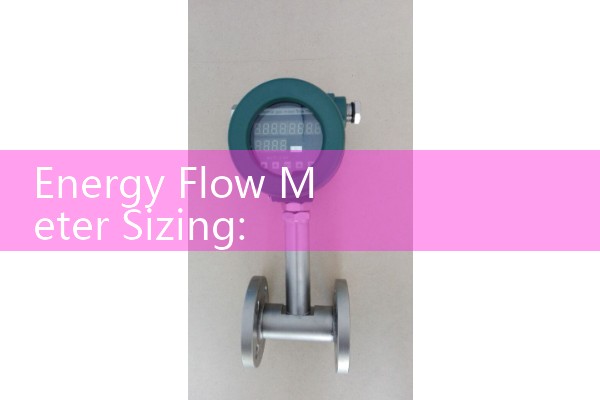
For DN15 to DN150, inline electromagnetic flow meters are common. They handle water and water-glycol mixtures. For DN200 and above, insertion electromagnetic flow meters or clamp-on ultrasonic flow meters can reduce cost. Clamp-on ultrasonic is good for retrofit because you do not cut the pipe. But clamp-on accuracy depends on pipe wall condition, pipe material, and flow profile.
Step Three: Select Temperature Sensors and Calculator
Most HVAC energy meters use two matched PT100 or PT1000 sensors. One sensor goes in the supply line. One goes in the return line. The pair must be matched to reduce uncertainty. A mismatch of 0.1 °C can create an energy error of 2 percent or more when delta T is 5 K.
Silver Automation Instruments can supply paired PT100 sensors in thermowells. The SIL-BTU calculator receives 4-20 mA or pulse from the flow meter and resistance values from the sensors. It reports kW, BTU per hour, tons, or GJ. Most customers request Modbus RTU output to the building management system. We also support BACnet gateways for HVAC projects.
Common HVAC Applications We See
A district cooling plant in Malaysia measured chilled water at DN300. The main line runs 600 m3/h at design load. We supplied an insertion electromagnetic flow meter with a matched PT100 pair and a wall mount calculator. The customer also connected an ultrasonic clamp-on meter to verify the insertion meter after commissioning.
In the Middle East we see many hotel and mall HVAC
In Southeast Asia a food processing plant needed hot water energy measurement at 90 °C. The line was DN40 and flow range was 1.2 to 8 m3/h. We supplied an inline electromagnetic flow meter with PTFE liner and 4-20 mA HART output. The liner material must match the temperature. Cold water can use hard rubber or PTFE. Hot water above 80 °C needs PTFE or PFA.
Model Selection for Specific Pipe Sizes and Fluids
For clean water, chilled water, and hot water from DN15 to DN150, use the Silver Instruments SIL-EMF series. It comes with compact or remote display, 4-20 mA HART, pulse, and optional Modbus RTU. For DN200 to DN1200 cooling water lines, use the SIL-Insertion electromagnetic series or SIL-UF clamp-on ultrasonic series. A SIL-BTU wall mount calculator pairs with two matched PT100 sensors.
Pressure matters too. A standard electromagnetic flow meter runs at 16 bar or 25 bar with a welded body. Tell us the pressure in bar. A chiller plant usually runs below 10 bar. A high rise condenser line in the Gulf may hit 25 bar during testing.
For boiler feed water or thermal oil, a Coriolis mass flow meter from Silver Instruments works but costs more. Most HVAC cooling and heating loops do not need Coriolis accuracy. Vortex and oval gear meters are not typical for HVAC water loops. We recommend them for steam, fuel oil, or chemical batching instead.
Installation Requirements That Affect Sizing
We recommend 5D straight pipe upstream and 3D downstream for electromagnetic flow meters. After a pump or a partially open valve, the velocity profile is disturbed. The meter may read high or low until the flow straightens.
Do not install the meter at the lowest point where air collects. Do not install it at the highest point where air pockets form. Air in a chilled water line causes the electrodes to lose contact and the meter output jumps. We have seen this on customer sites many times. A chiller restarts after maintenance and the flow meter output swings because air is trapped in the sensor tube.
For PT100 sensors, install them in thermowells in the same plane. Immerse the probe tip at least half the pipe diameter into the flow. A short insertion depth misses the average temperature.
FAQ: Energy Flow Meter Sizing for HVAC
What flow range should I provide for sizing? Give the minimum and maximum flow in m3/h or L/s. If you only have design flow, share the chiller capacity in kW or tons and the design delta T. We can estimate the minimum from turndown.
Pipe size is DN150. Can I use one DN150 meter for both chilled and hot water? Usually yes if the fluid is water or a glycol mix below the liner temperature limit. Specify the maximum temperature. We select a liner and electrode that cover both.
Do I need a separate BTU calculator or can the flow meter do it? Some Silver Instruments electromagnetic flow meters have built in temperature inputs and thermal energy totalization. For distributed systems we often supply an external calculator with pulse inputs and Modbus RTU.
What accuracy can I expect in an HVAC energy meter? A well sized electromagnetic flow meter gives plus or minus 0.5 percent of reading or better. The matched PT100 pair and calculator add uncertainty. Total system accuracy often falls around plus or minus 1 to 2 percent of reading depending on delta T.
Can you match an existing HVAC control system protocol? Yes. We supply 4-20 mA, pulse, Modbus RTU, and BACnet gateways. Send us your BMS points list and we will recommend the output.
For a fast size check, send us the thermal load in kW or BTU per hour, pipe size (DN), fluid type, supply and return temperature in °C, and pressure in bar. Our engineers will recommend a flow meter and sensor pair. Contact Silver Automation Instruments at Tel +86-25-68650347 or WhatsApp +86-25-52155837. WeChat +86 15365082610. Website flow-meter.com.au.
 Hot Product
 Related AD