

 Current position > News detail
『Flow Meter Electronic Configuration: Setting Up Smart Signal Converters and Data Portals』Related information(v cone flow meter|rotary gas meter|gallon meter|gear meter|metal tube rotameter|glass tube rotameter|nutating disk meter|transit time ultrasonic flow meter|wedge flow meter|pd meters|hydraulic flow meter|ultrasonic water flow meter|water flow meter|air flow meter|magnetic water flow meter|oxygen flow meter|gas flow meter|argon flow meter|air velocity meter|gasoline flow meter|fuel flow meter|ultrasonic water meter|digital water meter|nitrogen flow meter|solid flow meter|Oxygen tank flow meter|digital water flow meter|diesel fuel flow meter|steam flow meter|02 flow meter|compressed air flow meter|oil flow meter|liquid flow meter)
Flow Meter Electronic Configuration: Setting Up Smart Signal Converters and Data Portals
Quick Answer: Smart signal converters turn raw sensor signals into 4-20 mA HART, RS485 Modbus, or pulse data. A data portal gives you remote access to flow rate, totalizer values, and alarm states without opening the panel. Silver Instruments supplies flow meters with preconfigured electronics for DN10 to DN300 lines and common industrial protocols.
Most engineers skip the signal converter setup at first. They focus on pipe size, pressure, and temperature. Then the flow meter arrives on site and the output does not match the PLC or SCADA. We have seen this in Vietnam, Indonesia, Saudi Arabia, and Mexico.
1. Match the Signal Converter to the Flow Meter Type
An electromagnetic flow meter needs an excitation current for the coils. A Coriolis mass flow meter needs drive gain control and phase shift measurement. An ultrasonic flow meter needs transit time processing. Do not treat all smart converters the same.
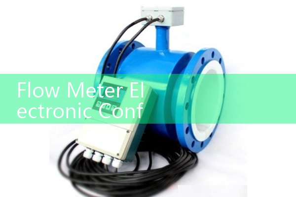
Silver Instruments electromagnetic flow meters use a compact converter mounted on the sensor or remote mounted up to 30 meters away. The converter reads conductivity, empty pipe conditions, and flow velocity. For clean water a conductivity above 20 µS/cm is enough. For demineralized water you need a special electrode setup or a different meter type.
A customer in the Philippines used a standard electromagnetic flow meter on demineralized water. The signal was unstable. The fix was a Coriolis meter because the conductivity was below 5 µS/cm and the process needed mass flow. This detail saved them a second site visit.
2. Configure the 4-20 mA HART Output First
Set the 4 mA point at the minimum flow range. Set the 20 mA point at the maximum flow range. Many users set 0 to 100 percent of the sensor limit. That reduces resolution for low flow. If your normal flow is 12 m³/h on a DN80 line, set 4 mA at 0 m³/h and 20 mA at 20 m³/h. That gives better analog resolution and faster control response.
HART 7 is the standard on most Silver Instruments flow meters. Use a HART handheld communicator or a USB modem with the free DTM. You can read flow rate, totalizer, temperature, and diagnostic codes over the same two wires.
In practice, HART is underused. A wastewater plant in Australia ran 4-20 mA only. The flow meter had HART but nobody connected it. After enabling HART, the team read diagnostic alerts in the control room. That reduced manual checks on 22 open channel meters.
Most Silver Instruments thermal mass flow meters include a PT100 input for gas temperature compensation. That reading can also be sent over HART as a secondary variable.
3. Set Pulse Output and RS485 Modbus for Totalizer Data
Use a pulse output when the PLC or batch controller needs total flow. Set the pulse unit in liters or cubic meters per pulse. Do not set a pulse rate faster than the input card can count. A common error is 1 pulse per liter on a high flow line. The counter overflows. We often set 1 pulse per 10 liters or 1 pulse per 100 liters for DN100 and above.
RS485 Modbus RTU carries flow rate, totalizer, and alarm bits over two cores. The baud rate, parity, and station ID must match the DCS or SCADA. Silver Instruments supports 1200 to 115200 baud. The default is 9600 baud, 8 data bits, no parity, 1 stop bit. But many projects change this in the drawing. Check the cable length. For RS485 runs over 500 meters use shielded twisted pair and a 120 ohm termination resistor at both ends.
A paint manufacturer in Southeast Asia used RS485 Modbus for solvent batching. They connected six oval gear flow meters to a PLC. The pulse output triggered the batch stop valves. The Modbus data fed the batch report system. That setup reduced overshoot from 3 percent to 0.5 percent on 200 liter batches.
4. Data Portal Setup in Three Steps
Step one is to collect the signal at the gateway. Use a 4-20 mA HART or Modbus RTU gateway that supports MQTT or HTTP. Step two is to push data to the portal with a fixed interval. We recommend 5 to 15 seconds for utility flow monitoring. Step three is to map tag names, units, and alarm thresholds in the porta
Silver Instruments flow meters do not lock you into one cloud. You can push data to your own SCADA, a local historian, or a cloud dashboard. For sites with poor internet, store data locally and sync when the connection returns. This works well for remote pump stations in the outback or islands in Indonesia.
Because many industrial sites block outbound MQTT ports, a simple HTTP post to the customer data portal is often more reliable. We have used this in a dairy plant in New Zealand. The plant pulled flow and temperature data from 30 Coriolis meters every 10 seconds. The portal displayed CIP cycles, product batch flow, and alarm events on one screen.
5. Common Field Mistakes
One mistake is grounding. An electromagnetic flow meter needs a good earth connection. On plastic pipes use grounding rings or electrodes. A water treatment plant in Malaysia saw unstable readings because the grounding ring was loose. Tightening it fixed the noise.
Another mistake is signal cable routing. Do not run the flow meter signal cable next to VFD motor cables. Use separate conduit and keep at least 300 mm spacing. We have seen 4-20 mA readings jump by 5 percent when a pump VFD started.
A third mistake is ignoring empty pipe detection. The converter may hold the last value or go to zero. Set the alarm output to tell the PLC when the pipe is empty. This prevents false dosing or false totalizer counts during pump stops.
6. Recommended Settings by Industry
For water and wastewater use electromagnetic flow meters with 4-20 mA HART and RS485 Modbus. Set the low flow cutoff at 0.1 m/s to zero the output during pipe drainage. Use IP68 converters for pit installations.
For chemical and food plants use Coriolis mass flow meters with mass flow in kg/h, temperature in °C, and density outputs over HART. If the fluid viscosity is above 250 cP, set the damping to 2 seconds or higher. In hazardous zones, order the converter with ATEX Zone 1 or Zone 2 certification.
For diesel, fuel oil, and lube oil use oval gear flow meters with pulse output. Use a K-factor from calibration. The K-factor often sits near 10 pulses per liter for small DN15 meters and less for DN50 meters. A fuel terminal in Peru used a preset batch controller on five loading arms. The Silver Instruments oval gear meters handled diesel from 10 to 200 liters per minute.
7. What to Send Us Before Ordering
Send us your pressure (bar), temperature (°C), pipe size (DN), and flow range. Include the process fluid, conductivity, viscosity, and the output signals you need. We will preset the converter at the factory and send you the wiring diagram with the meter.
Contact Silver Automation Instruments. Tel: +86-25-68650347, WhatsApp: +86-25-52155837, WeChat: +86 15365082610. Visit flow-meter.com.au for flow meter electronic configuration examples.
FAQ
Q: What does a smart signal converter do on a flow meter?
A: It converts the raw sensor signal into standard outputs such as 4-20 mA HART, RS485 Modbus RTU, or pulse. It also stores calibration data and diagnostic alarms.
Q: Can one data portal handle different flow meter types?
A: Yes. Use a gateway that reads HART, Modbus, and pulse inputs. The portal only needs tag names, units, and alarm limits. This works for electromagnetic, Coriolis, ultrasonic, vortex, and oval gear meters.
Q: What is the best output for a PLC on a water line?
A: 4-20 mA HART is the most common. It carries flow rate and diagnostic alerts over two wires. Add RS485 Modbus if you want totalizer and alarm bits without extra wiring.
Q: Can you preset the flow meter electronics before shipping?
A: Yes. Send us your pressure, temperature, pipe size, and flow range. We set the 4 mA and 20 mA points, pulse unit, damping time, and communication parameters before dispatch.
Q: Which flow meter should I use for low conductivity water?
A: Use a Coriolis mass flow meter or an ultrasonic meter if conductivity is below 5 µS/cm. Electromagnetic flow meters need a minimum conductivity, usually 5 to 20 µS/cm depending on the electrode design.